In this tutorial we will run a MySQL database on Amazon Elastic Kubernetes Service (EKS) and use the cluster with Toad Edge 2.0.2.
Amazon Elastic Kubernetes Service (EKS), a recent addition to AWS, is a managed service for the Kubernetes container orchestration platform. As a primer on Kubernetes terminology, a Pod is an abstraction for a set of collocated containers with its own networking and filesystem. A Pod is the smallest atomic unit Kubernetes manages. A replication controller maintains a specified number of Pod replicas for a container image specification. A service is an abstraction for targeting and directing client traffic to a set of Pods that are identified using label selectors.
In an earlier tutorial we created an EKS cluster in a VPC and joined two worker nodes to the cluster. In this continuation article we shall create a Kubernetes service and replication controller for MySQL Database. Subsequently we shall connect to the database with Toad Edge 2.0.2. This article has the following sections.
Creating a Kubernetes Replication Controller for MySQL
Creating a Kubernetes Service for MySQL
Creating a Connection
Creating a Table
Querying Table
Exporting Result Set
Creating a Kubernetes Replication Controller for MySQL
Kubernetes manages Docker containers. A replication controller is an object that defines the Docker container spec and manages the number of Pod replicas. A replication controller is defined in a configuration file in JSON or YAML format. A service makes use of selector labels to access the Pods managed by a replication controller. These selector labels must match between a replication controller and a service.
Create a configuration file mysql-rc.yaml and copy the following listing to the file.
—–
apiVersion: v1
kind: ReplicationController
metadata:
labels:
app: mysqlapp
name: mysql-rc
spec:
replicas: 1
selector:
app: mysqlapp
template:
metadata:
labels:
app: mysqlapp
spec:
containers:
–
env:
–
name: MYSQL_ROOT_PASSWORD
value: mysql
image: mysql
name: mysql
ports:
–
containerPort: 3306
The preceding configuration file defines a replication controller as indicated by the kind field. The metadata field specifies the labels of the replication controller; the labels default to the Pod labels if not set. The spec field defines the specification of the replication controller. The spec field further defines other fields including replicas, selector, and template. The replicas field specifies the number of “desired” replicas. By “desired” it is implied that if some replicas fail the replication controller starts new replicas to bring the number to the desired level. The default number of replicas is 1. An explicit 0 may be specified for replicas. The selector field specifies the label keys and values that must match in a Pod template to be managed by the replication controller. If selector labels are empty these default to the labels of the Pod template. The template field specifies the Pod that is managed by the replication controller and defines its own metadata and spec fields to define the Pod. Themetadata field defines the labels and the spec field describes the Pod and defines several fields including the restartPolicy field for the restart policy (default being Always) and the containers field, which defines a list of containers including the container name, Docker image, environment variables, and ports for each container. The schema for the replication controller defines all the fields.
For the MySQL database the containers field defines container name as mysql, image as mysql, environment variables as MYSQL_ROOT_PASSWORD, and port as 3306 for the container port.
To create a replication controller run the following command.
kubectl create -f mysql-rc.yaml
As the command output indicates, a replication controller gets created.
C:\ElasticKubernetesService\MySQL>kubectl create -f mysql-rc.yaml
replicationcontroller “mysql-rc” created
List the replication controllers with the following command.
kubectl get rc
A replication controller for MySQL database gets listed.
C:\ElasticKubernetesService\MySQL>kubectl get rc
NAME DESIRED CURRENT READY AGE
mysql-rc 1 1 1 17s
Describe the replication controller.
kubectl describe rc mysql
The replication controller detail gets listed, including the Pods managed by the rc, the containers described by the rc, the number of replicas, the Pods status, and the Events.
C:\ElasticKubernetesService\MySQL>kubectl describe rc mysql
Name: mysql-rc
Namespace: default
Selector: app=mysqlapp
Labels: app=mysqlapp
Annotations: <none>
Replicas: 1 current / 1 desired
Pods Status: 1 Running / 0 Waiting / 0 Succeeded / 0 Failed
Pod Template:
Labels: app=mysqlapp
Containers:
mysql:
Image: mysql
Port: 3306/TCP
Host Port: 0/TCP
Environment:
MYSQL_ROOT_PASSWORD: mysql
Mounts: <none>
Volumes: <none>
Events:
Type Reason Age From Message
—- —— —- —- ——-
Normal SuccessfulCreate 19s replication-controller Created pod: mysql-rc-
7p7n6
List the Pods.
kubectl get pods
A single Pod gets listed. The STATUS should be “Running” to be able to use the Pod. The READY column lists the number of Pods/Desired number of Pods. A value of 1/1 implies one Pod out of the desired 1 Pods is ready.
C:\ElasticKubernetesService\MySQL>kubectl get pods
NAME READY STATUS RESTARTS AGE
mysql-rc-7p7n6 1/1 Running 0 36s
Creating a Kubernetes Service for MySQL
In this section we shall create a service that defines the access policy of the set of Pods that are targeted by the service. Create a configuration file mysql-service.yaml and copy the following listing to the file.
—
apiVersion: v1
kind: Service
metadata:
labels:
app: mysqlapp
name: mysql
spec:
ports:
–
port: 3306
selector:
app: mysqlapp
type: LoadBalancer
The kind field set to Service is what makes the configuration a service. The metadata field defines the labels and the name field the service name. The spec field defines the Service specification, including the service type, ports exposed by the service, and selector label/s used to target Pods to route client traffic to. The service configuration files must be conformant with the service schema. Service type is set to LoadBalancer which creates an external AWS Elastic Load Balancer (classic) for the service to balance client traffic on the external VM instances (EC2). Create a service with the following command.
kubectl create -f mysql-service.yaml
As the command output indicates, a service gets created.
C:\ElasticKubernetesService\MySQL>kubectl create -f mysql-service.yaml
service “mysql” created
List the services, and the mysql service gets listed. The mysql service defines anExternal-IP in addition to the Cluster-IP. The Cluster-IP is a cluster-internal IP for load balancing on the endpoints. The External-IP routes client traffic to Cluster-IP.
C:\ElasticKubernetesService\MySQL>kubectl get services
NAME TYPE CLUSTER-IP EXTERNAL-IP PORT(S)
AGE
kubernetes ClusterIP 10.100.0.1 <none> 443/TCP
2h
mysql LoadBalancer 10.100.135.227 ad865be0b99e7… 3306:31454/TCP
15s
We would need the External-IP to access the service, and it is abbreviated in the services listed. Describe the service with the following command.
kubectl describe svc mysql
C:\ElasticKubernetesService\MySQL>kubectl describe svc mysql
Name: mysql
Namespace: default
Labels: app=mysqlapp
Annotations: <none>
Selector: app=mysqlapp
Type: LoadBalancer
IP: 10.100.135.227
LoadBalancer Ingress: ad865be0b99e711e8a0940a703b0aa1e-1393945137.us-east-1.
elb.amazonaws.com
Port: <unset> 3306/TCP
TargetPort: 3306/TCP
NodePort: <unset> 31454/TCP
Endpoints: 192.168.168.156:3306
Session Affinity: None
External Traffic Policy: Cluster
Events:
Type Reason Age From Message
—- —— —- —- ——-
Normal EnsuringLoadBalancer 37s service-controller Ensuring load balancer
Normal EnsuredLoadBalancer 35s service-controller Ensured load balancer
Copy the LoadBalancer Ingress value (ad865be0b99e711e8a0940a703b0aa1e-1393945137.us-east-1.elb.amazonaws.com) from the service description as we shall need it in the next section to create a connection.
Creating a Connection
To create a connection select Connect>New Connection as shown in Figure 1.
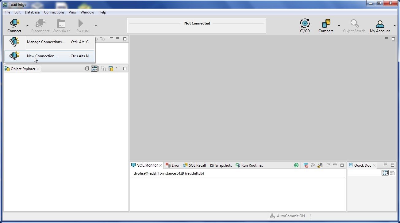
Figure 1. Connect>New Connection
In New Connection wizard select Database Platform as MySQL as shown in Figure 2 and click on Next.
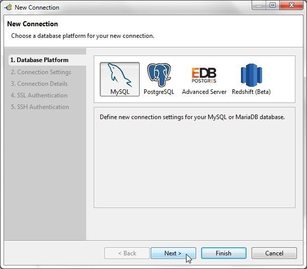
Figure 2. Selecting Database Platform as MySQL
In Connection Settings the default settings are shown in Figure 3 and we need to modify some of these.
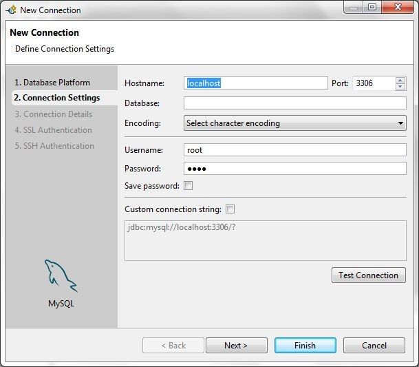
Figure 3. Default Connection Settings
Set Hostname to the External-IP of the service or the LoadBalancer Ingress ad865be0b99e711e8a0940a703b0aa1e-1393945137.us-east-1.elb.amazonaws.com (the value would be different for different users) as obtained from the service description and as shown in Figure 4. Set Database to mysql. Specify the Password for the root user as configured in the MYSQL_ROOT_PASSWORD environment variable in the replication controller configuration. Click on Test Connection to test the connection.
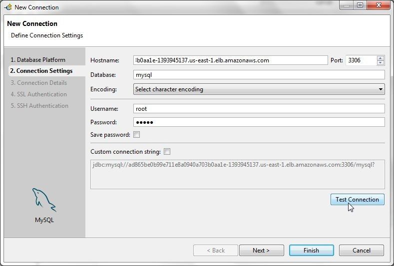
Figure 4. Connection Settings
A message Connection is OK gets displayed if a connection gets established, as shown in Figure 5. Click on Next.
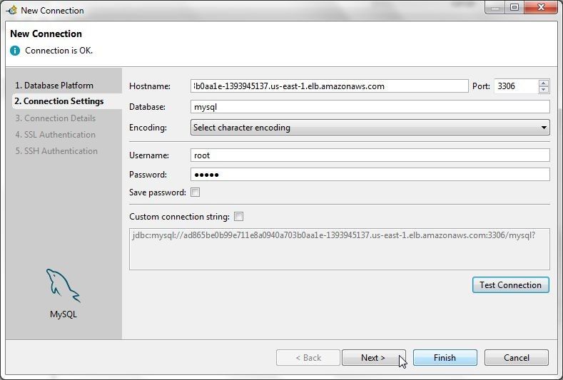
Figure 5. Connection is OK
In Connection Details select the option Enable Autocommit as shown in Figure 6.
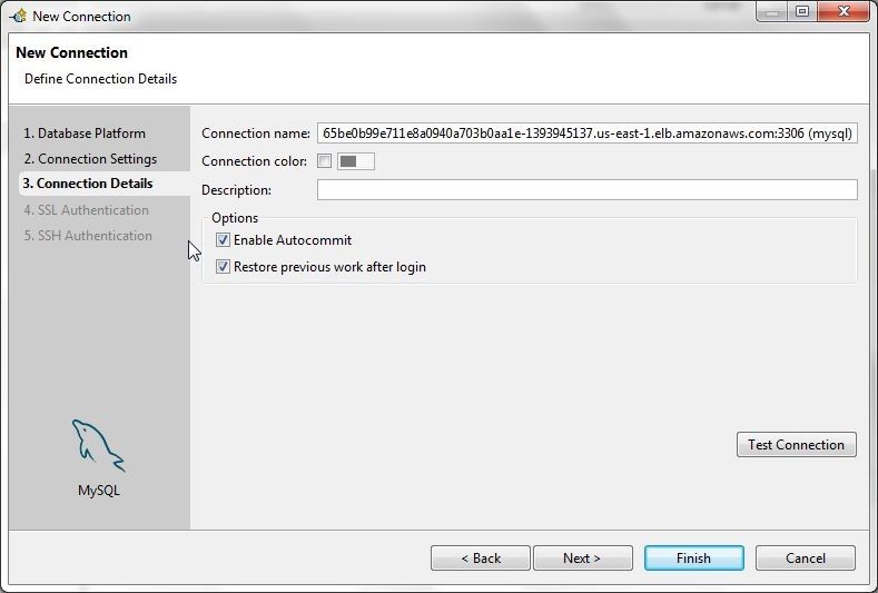
Figure 6. Enabling Autocommit
Optionally specify a more suitable connection name (in terms of shorter or other factor) as shown in Figure 7 and click on Finish.
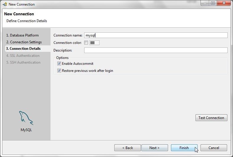
Figure 7. Completing Connection Details
A new connection gets created and added to the Connections view, as shown in Figure 8. A SQL Worksheet gets associated with the connection. The Object Explorer lists the Databases with themysql database as the default or active database. AutoCommit is shown to be ON in the lower section.
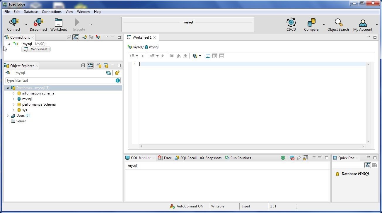
Figure 8. New Connection
Creating a Table
In this section we shall create a database table called wlslog using the following data, in which the first row is the column headers row.
LOGID,CATEGORY,TYPE,SERVERNAME,CODE,MSG
1,Notice,WebLogicServer,AdminServer,BEA-000365,Server state changed to STANDBY
2,Notice,WebLogicServer,AdminServer,BEA-000365,Server state changed to STARTING
3,Notice,WebLogicServer,AdminServer,BEA-000365,Server state changed to ADMIN
4,Notice,WebLogicServer,AdminServer,BEA-000365,Server state changed to RESUMING
5,Notice,WebLogicServer,AdminServer,BEA-000361,Started WebLogic AdminServer
6,Notice,WebLogicServer,AdminServer,BEA-000365,Server state changed to RUNNING
7,Notice,WebLogicServer,AdminServer,BEA-000360,Server started in RUNNING mode
Save the preceding listing to the wlslog.csv file. To create a table right-click on Tables in Object Explorer and select New Table as shown in Figure 9.
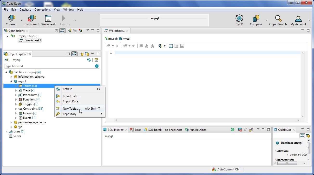
Figure 9. Tables>New Table
In the New Table wizard specify a Table name (wlslog) with the Database selected as mysql as shown in Figure 10. Keeping other settings to the default, click on Next.
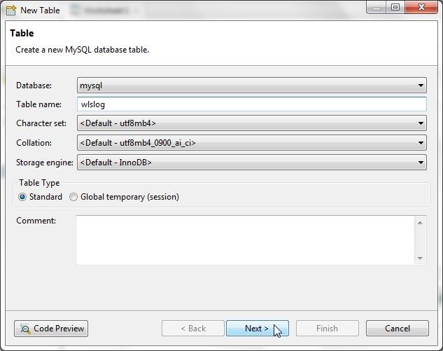
Figure 10. New Table Wizard
Next, add table columns. Click on New… to add a column as shown in Figure 11.
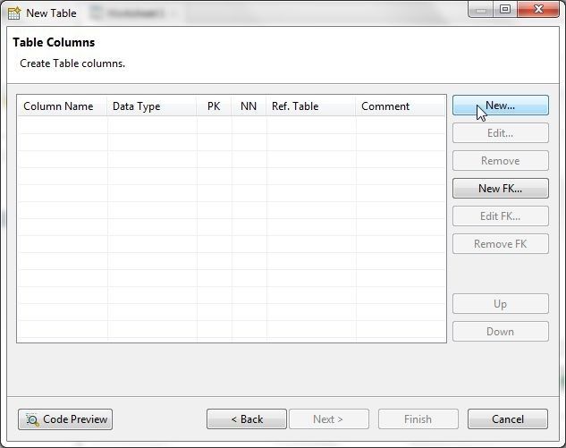
Figure 11. New Table>Table Columns>New
In the New Column wizard specify a column name (logid) in the Name field and select a Data Type as INT as shown in Figure 12. As logid is a primary key column, select the checkboxes Primary Key, Not Null, and Autoincrement. Click on OK+Add to add the column and open the New Column wizard to add another column.
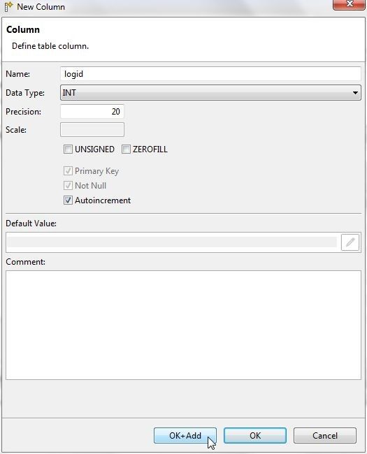
Figure 12. New Column Wizard
After adding each of the other columns category, type, servername, code click on OK+Add and after adding the last column msg click on OK as shown in Figure 13. The Data Type should be set toVARCHAR for each of the other columns. The column size may need to increase from the default value (20). As an example the msg field size has been set to 255.
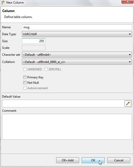
Figure 13. New Column>OK
In New Table all table columns are shown with their data type, as shown in Figure 14. Click on Finish.
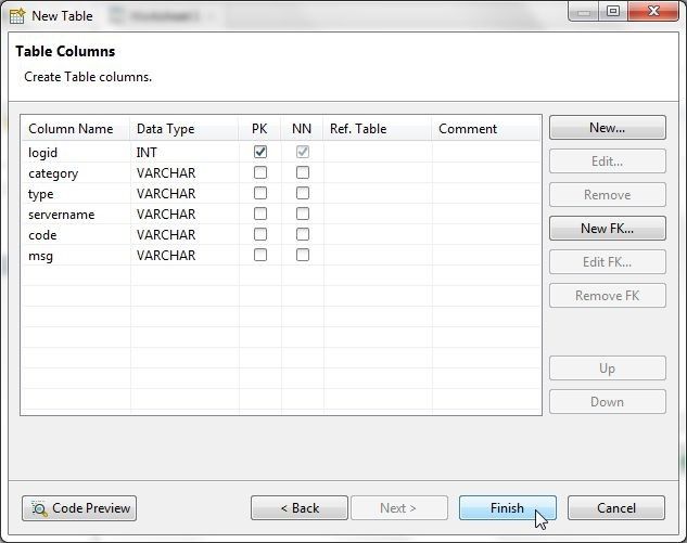
Figure 14. New Table>Finish
The new table wlslog gets created, as shown in Figure 15. The table and its columns are listed in Object Explorer.
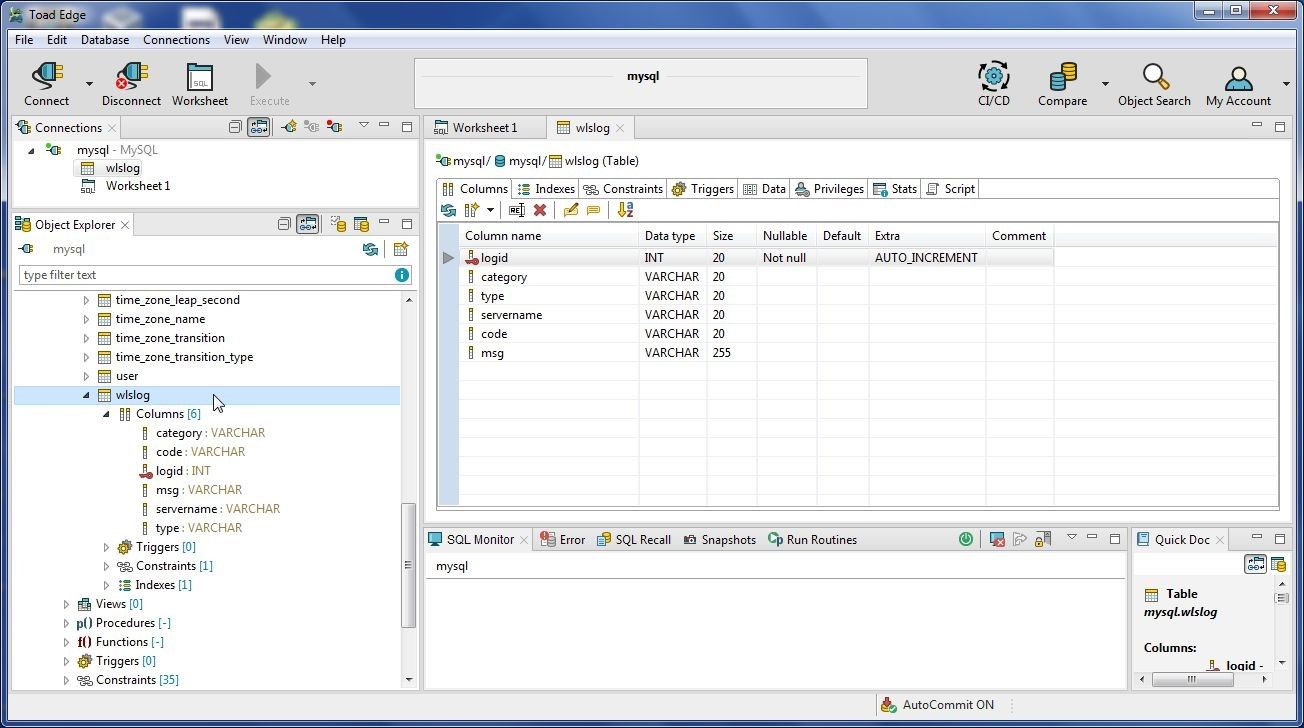
Figure 15. Table wlslog created
Next, add table data; for which, right-click on table and select Import Data as shown in Figure 16.
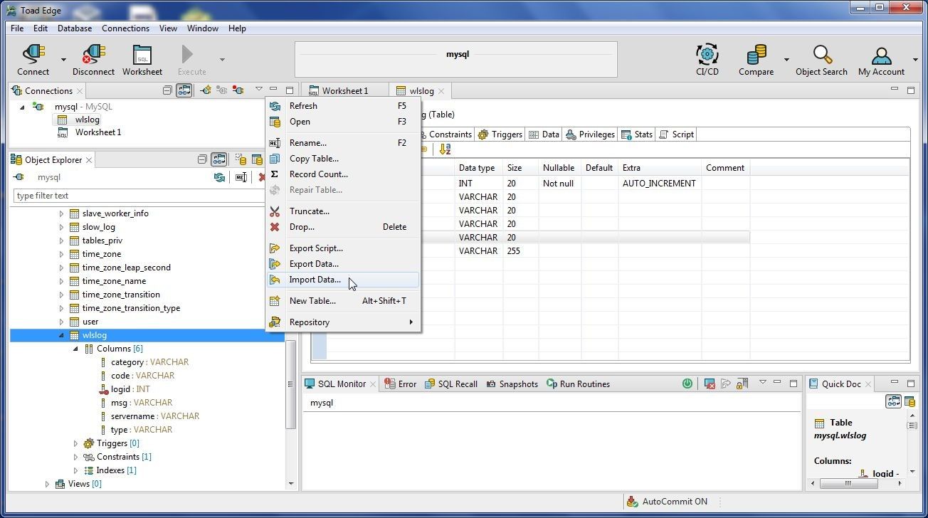
Figure 16. wlslog>Import Data
The Import Data wizard gets started, as shown in Figure 17. Click on the selector button (…) for the Source field and select the wlslog.csv file in the Select File dialog and click on Open. With the wlslog.csv file selected, click on Next.
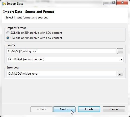
Figure 17. Import Data
In CSV Settings the Destination Database Table should be wlslog, as shown in Figure 18. The CSV Format Settings for field delimiter, text delimiter and escape character are specified, and as these are the settings in the wlslog.csv file we don’t need to modify. Select the checkbox for Skip First Row for Column Header. The Data Format settings for Date Format, Time Format don’t need to be modified, as the data being imported does not include date- or time-format data. The Data Format Preview displays the data to be imported. Click on Finish.
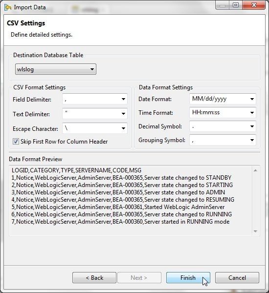
Figure 18. Import Data>Finish
The data should get imported. If data or a record does not get imported a Data Processing Error dialog gets displayed, as shown in Figure 19. The error detail is also listed and the option to either continue or terminate is provided. Select the option Ignore all errors and click on Continue.
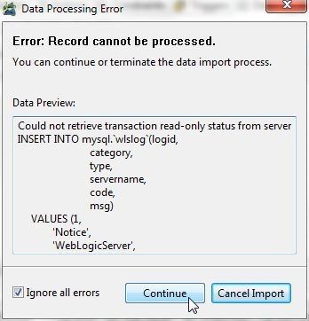
Figure 19. Data Processing Error
The Data Import Result dialog indicates that data import has finished with errors and warnings, as shown in Figure 20. With the Refresh data and Open log file options selected, click on Close.
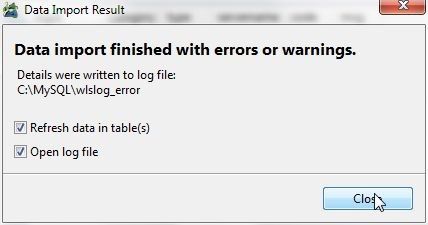
Figure 20. Data Import Result
For the data to display we need to click on Refresh as shown in Figure 21.
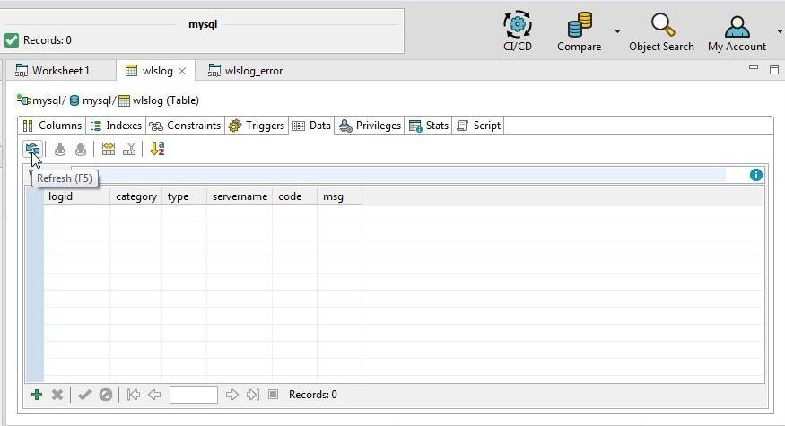
Figure 21. Refresh
The data gets displayed in the Data tab, as shown in Figure 22. As the import of the first record indicated an error, the first row is not listed.
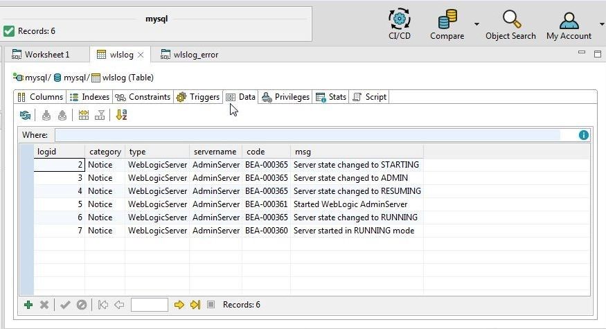
Figure 22. Data imported
Next, we shall demonstrate another feature that imports or adds a row of data at a time. We shall add the first record that did not get added with data import. Position the cursor on the first row and click on Add Row as shown in Figure 23.
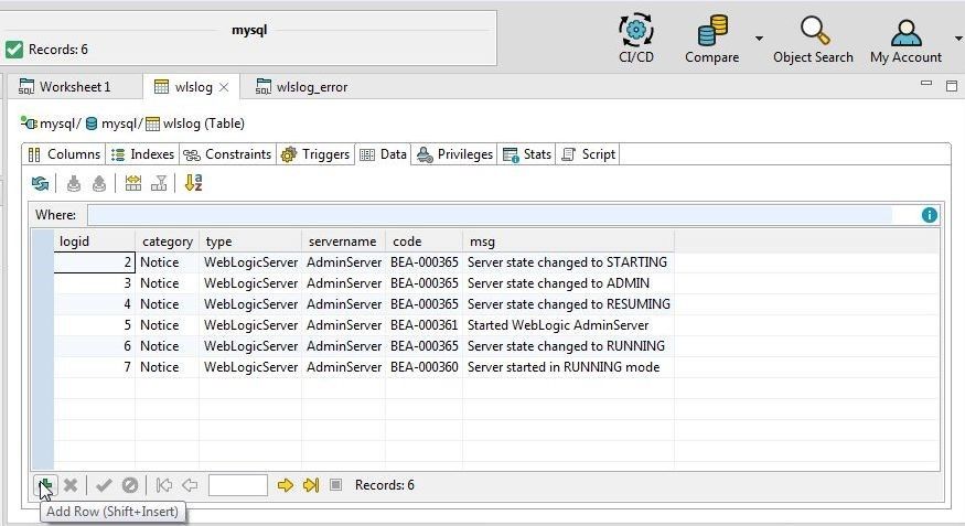
Figure 23. Add Row
An empty row gets added, as shown in Figure 24. To add values for the first record, either the value may be added directly in the field provided or the Define in Editor may be selected, as shown in Figure 24.
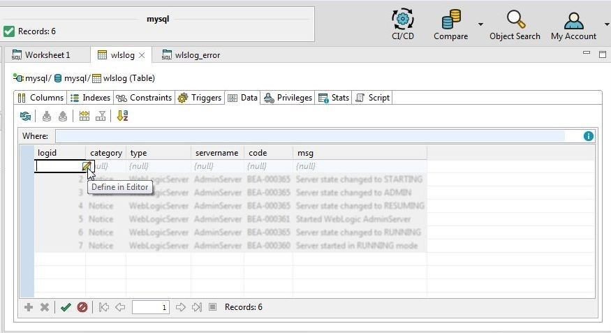
Figure 24. Define in Editor
In the dialog displayed, specify a value for the logid column of type INT(20) and click on OK as shown in Figure 25.
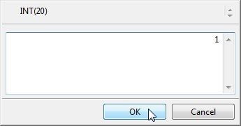
Figure 25. Adding logid Value
For the category column select the value from the list of values displayed as shown in Figure 26.
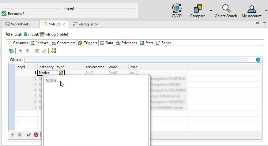
Figure 26. Adding Value in category Field
Similarly, add values for thetype and servername fields. For the code column start to add a value with “B, as we know the code value starts with a “B”, and select a value from the list displayed as shown in Figure 27.
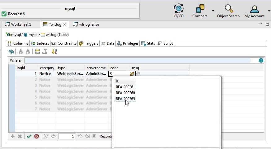
Figure 27. Adding code Column Value
For the msg column click on Define in Editor as shown in Figure 28 to add a value.
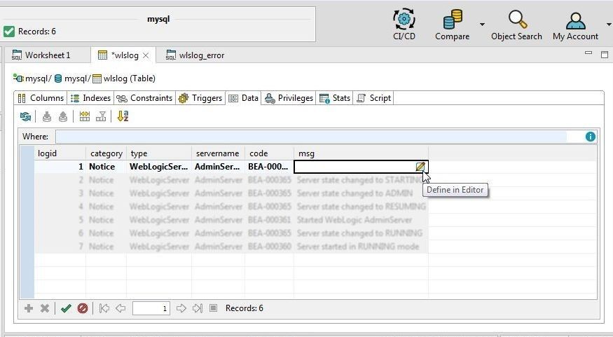
Figure 28. Selecting Define in Editor for msg
Add a msg value as shown in Figure 29 and click on OK.
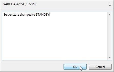
Figure 29. Adding msg
With a new record added, click on Refresh as shown in Figure 30.
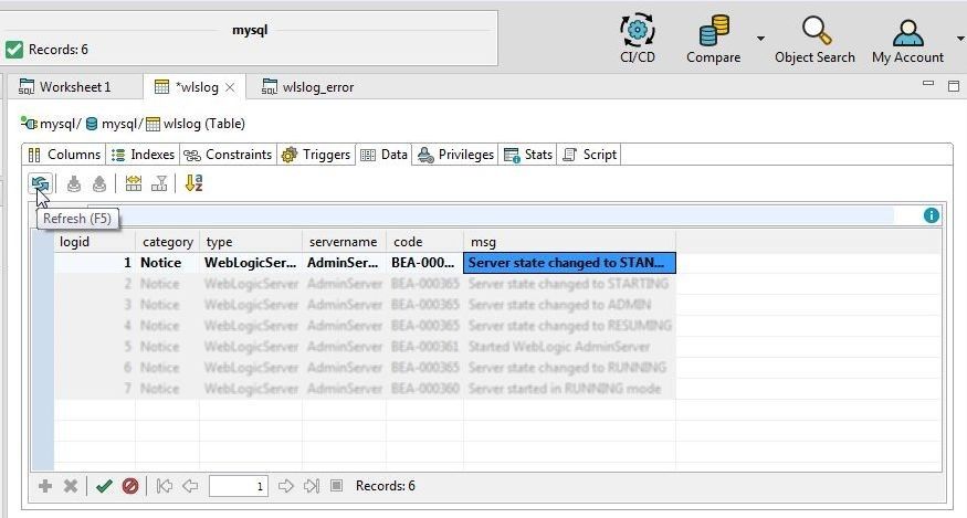
Figure 30. Refreshing Data
A Commit dialog gets displayed indicating that the data needs to be committed, as shown in Figure 31.
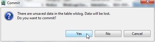
Figure 31. Commit
The new data should get committed. If the data does not get committed a Detail save failed dialog gets displayed, as shown in Figure 32.
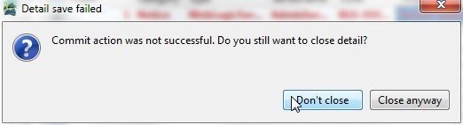
Figure 32. Detail Save Failed
The Error tab lists the error message. Click on Apply Changes as shown in Figure 33 to apply changes.
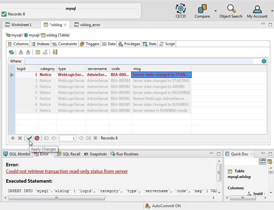
Figure 33. Apply Changes
Click on Refresh again as shown in Figure 34 to refresh data. All the data added and imported should get displayed.
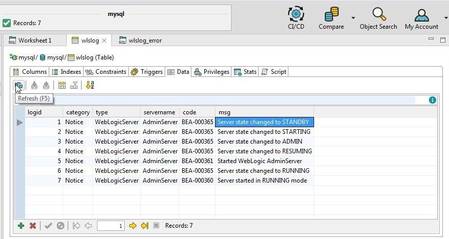
Figure 34. Data Refreshed
Querying Table
In this section we shall query the table using the following SQL query.
SELECT * FROM wlslog;
First, open a new SQL Worksheet by selecting Open SQL Worksheet from the toolbar as shown in Figure 35.
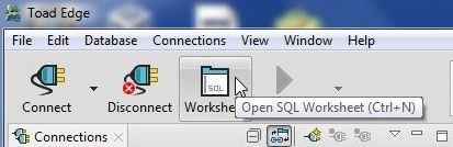
Figure 35. Open SQL Worksheet
Add SELECT in the SQL worksheet and select “*” from the code-assist drop-down as shown in Figure 36.
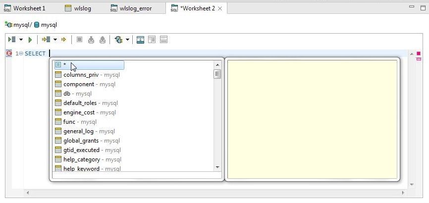
Figure 36. Adding SQL Statement using Code-Assist
After adding “*” add a space and select FROM from the code-assist drop-down as shown in Figure 37.
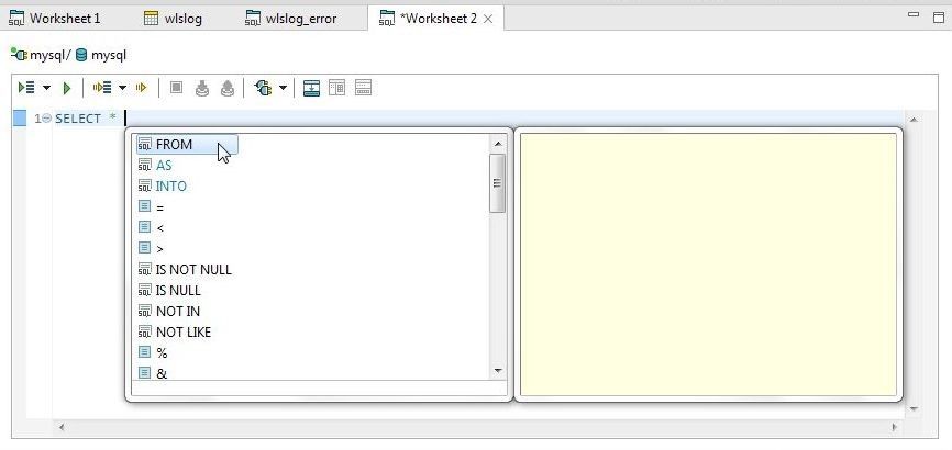
Figure 37. Selecting FROM with Code Assist
Add another space and select wlslog from the code-assist drop-down as shown in Figure 38.
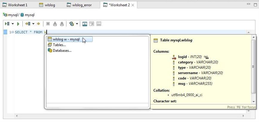
Figure 38. Selecting Table wlslog
The complete SQL statement gets added, as shown in Figure 39.
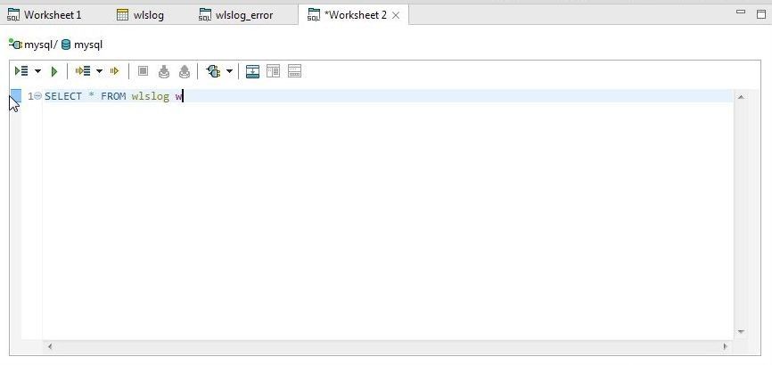
Figure 39. Complete SQL Statement
Click on Execute SQL Statement as shown in Figure 40.
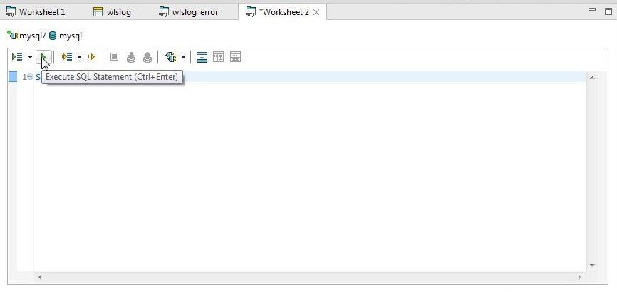
Figure 40. Execute SQL Statement
The result set gets displayed, as shown in Figure 41.
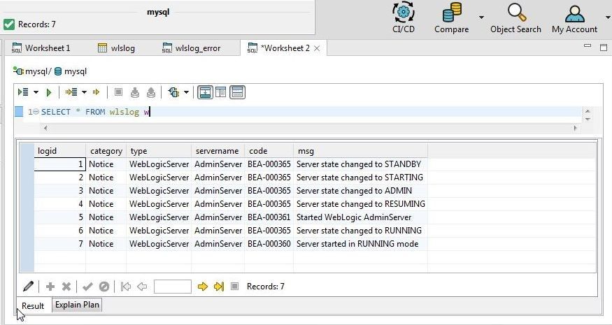
Figure 41. Result Set
Exporting Result Set
Result data may be exported to CSV, SQL, HTML or XML. To export the complete result set to CSV or SQL, right-click in the Result set and select Export Result. To export a selection of data from the result, select the data records to be exported. Multiple rows of data or a range of rows may be selected with Shift+Row. As an example, select all the rows in the result by selecting the first row, selecting Shift and selecting the last row. Right-click and select Export Selection>HTML as shown in Figure 42.
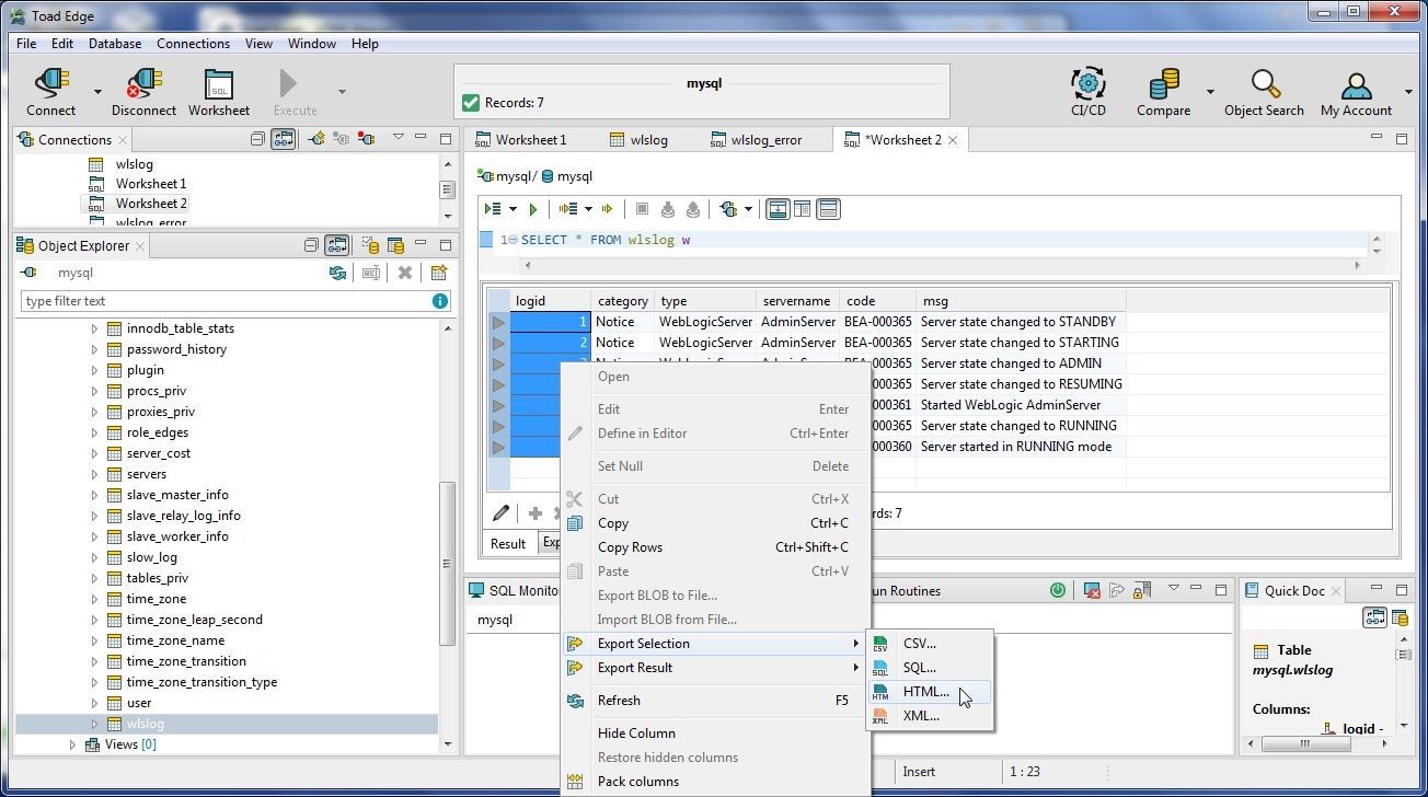
Figure 42. Export Selection>HTML
In the Save As dialog specify a File name (wlslog) and click on Save. The wlslog.html is shown in Figure 43.
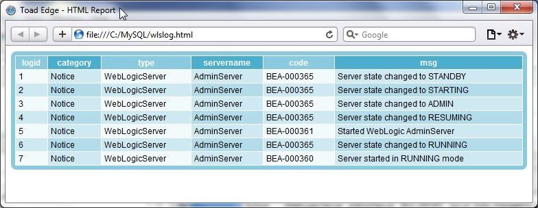
Figure 43. Exported HTML
A single data record may also be imported, as shown in Figure 44.
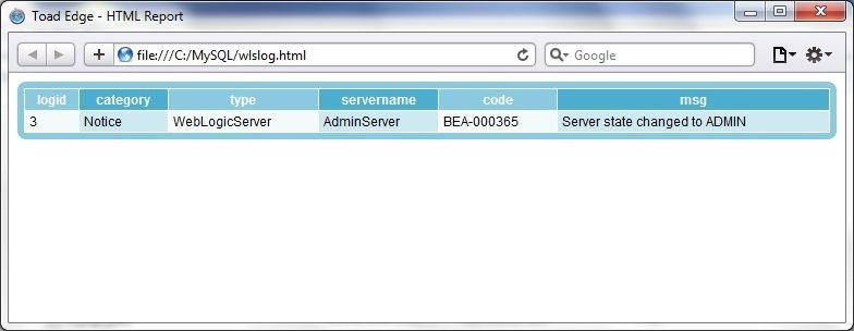
Figure 44. Single Row Export
Deleting Cluster
To delete the EKS cluster select the cluster and click on Delete as shown in Figure 45.
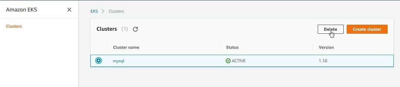
Figure 45. Deleting Cluster
Click on Delete in the verification dialog as shown in Figure 46.
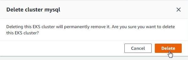
Figure 46. Delete cluster dialog
The EKS cluster starts to get deleted, as shown in Figure 47.
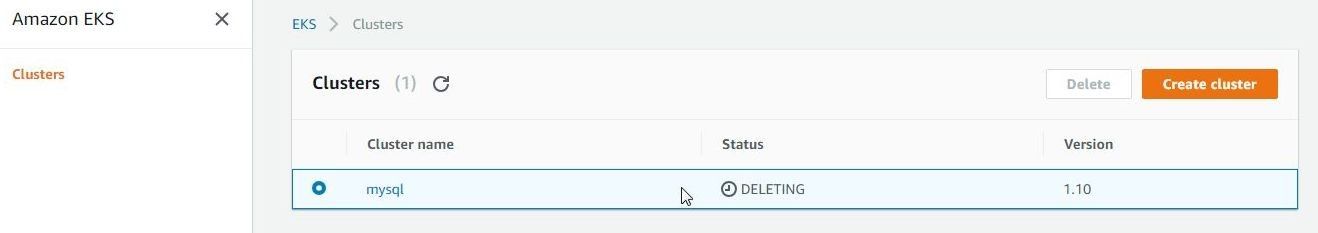
Figure 47. Deleting Cluster
The cluster gets deleted, as shown in Figure 48.
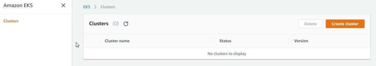
Figure 48. Cluster deleted
Any Scaling groups, launch configurations, and CloudFormation stacks started for the cluster would need to be deleted separately.
Conclusion
In two articles we have discussed creating an EKS cluster to run a MySQL database Kubernetes service and using the cluster with Toad Edge 2.0.2. While Amazon EKS is a managed service for Kubernetes a client tool is needed to access a database running on EKS. Toad Edge is an integrated development environment for open source databases with the concomitant benefits of a connection wizard, object explorer, and other wizards to access open source databases, run SQL statements and explore database objects.
Start the discussion at forums.toadworld.com